- Published on
Networking Interfaces and cables | RJ45, Ethernet Standard, Single Mode and Multi Mode Fiber

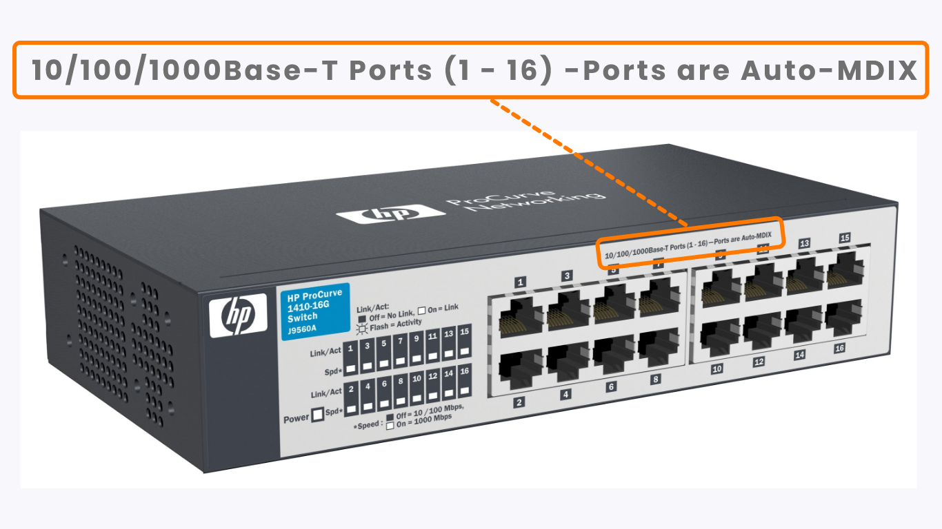
The above image shows the front of a network switch, zoomed in on a label that reads '10/100/1000Base-T Ports(1-24)-Ports are Auto-MDIX'. '1-24' is easy enough to understand, those are the port numbers.
How about '10/100/1000Base-T' and 'Ports are Auto-MDIX'? If you're not familiar with networking yet, chances are you don't understand what these labels mean. If that's the case, be sure to follow this article to learn!
RJ-45 Interface / Port
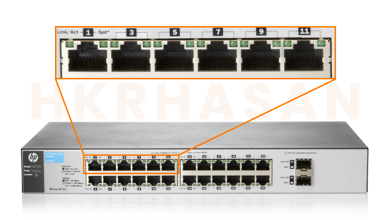
Even if you're no networking expert, I'm sure you've seen network ports like these before. They are called RJ-45 ports. RJ stands for Registered Jack. These are the most common type of network interface, and are used to connect network devices together with copper cables.
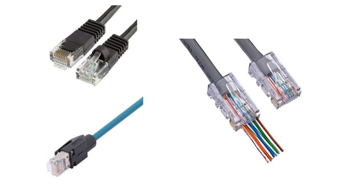
These are some examples of RJ-45 connectors, which are used to connect to the RJ-45 ports in the previous image. They com with various designs, but the connector is always the same. If you look closely, you can see that there are 8 metal pins in an RJ-45 connector. Remember that!
To talk about interfaces and cables, we need to talk about Ethernet. You've probably heard the term Ethernet before, and have probably heard and used the term Ethernet cable before, but what exactly is Ethernet?
What is Ethernet?
Ethernet is a collection of network protocols and standards, which are rules and standards which device manufacturers agree upon, for example the shape of RJ-45 ports and connectors are an industry standard.
Why do we need network protocols and standards?
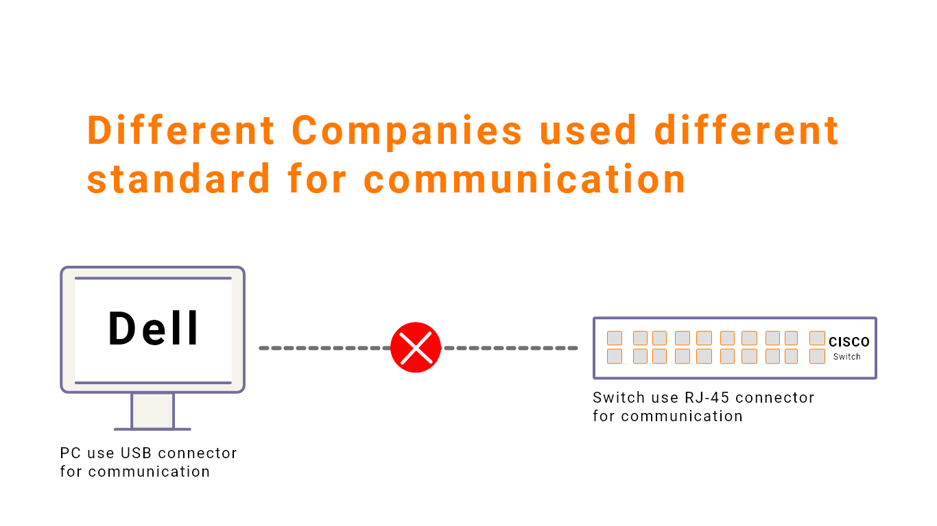
What would happen if there were no industry standards, and each company made their own rules about how devices should communicate over a network? To put it simply, it wouldn't work. If you have a Dell PC and a Cisco switch, and each of them requires a different kind of connector and cable, you wouldn't be able to connect the two devices.
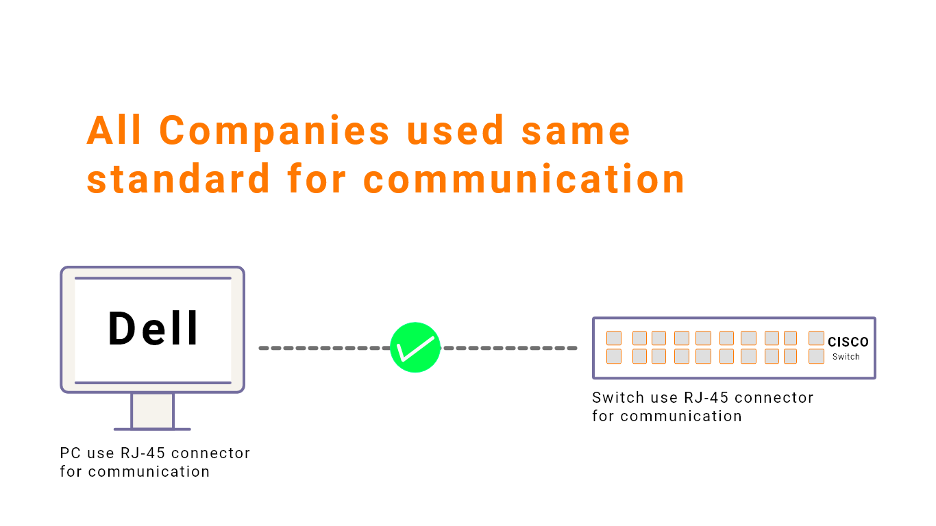
Industry standards are important to ensure that any PC will be able to connect and operate with any network switch, any switch will be able to connect to and operate with any router, etc.
When did Ethernet become industry standard?
Ethernet was first defined in the IEEE 802.3 standard in 1983. The IEEE (Institute of Electronics Engineers) is a professional association for electronic engineering and electrical, located in America.
Many of the protocols and standards we use in networks today, such as Ethernet, are defined by IEEE. You can read about the IEEE on Wikipedia
Different Between Bits and Byte.
Before going on to explain some of the Ethernet standards we use, we need to define bits and bytes, two terms you've probably heard before.
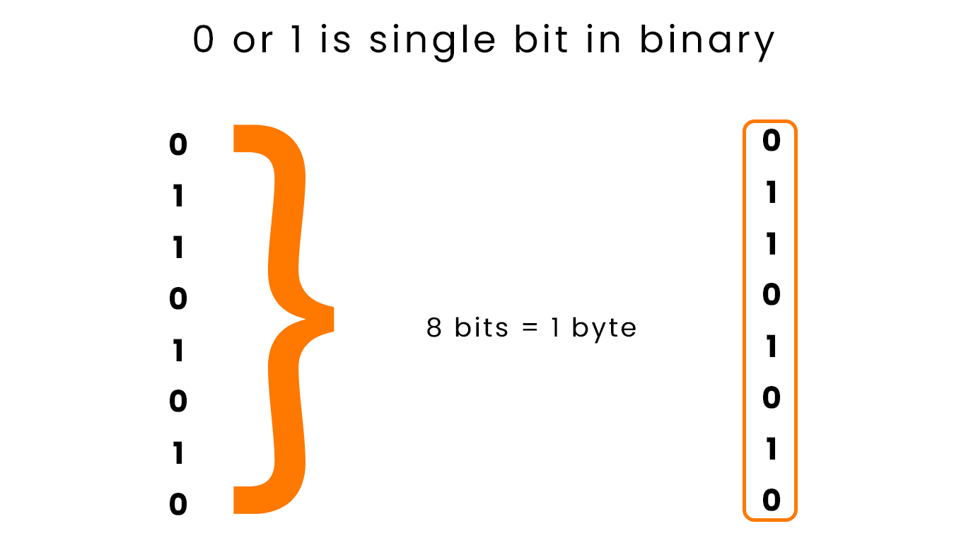
Computer think in Binary, a series of 0's and 1's. This web page, a video you watch on Youtube, a Skype call over the internet, all of them are series of bits (0 or 1) whcih are interpreted by your computer.
Another important term is Byte. A Byte is simply 8 bits, and we often measure the size of files, in bytes rather than bits. For example, if a file is 1 gigabytes in size, it is 1 billion bytes in size. Because 1 byte is 8 bits, it means that file is 8 billion bits in size.
How network speed measured?
However, network speed is not measured in bytes per second. Network speed is measured in bits per second, for example kilobits per second(Kbps), megabits per second(Mbps), gigabits per second(Gbps), etc.
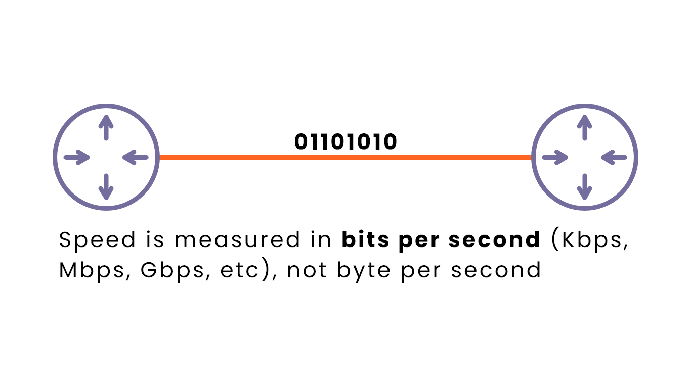
Think of bits of data being send along a wire like in the image. They are send received one bit at a time (at a very rapid pace!). Changes in the electrical signal are used to represent a series of 0's and 1's.
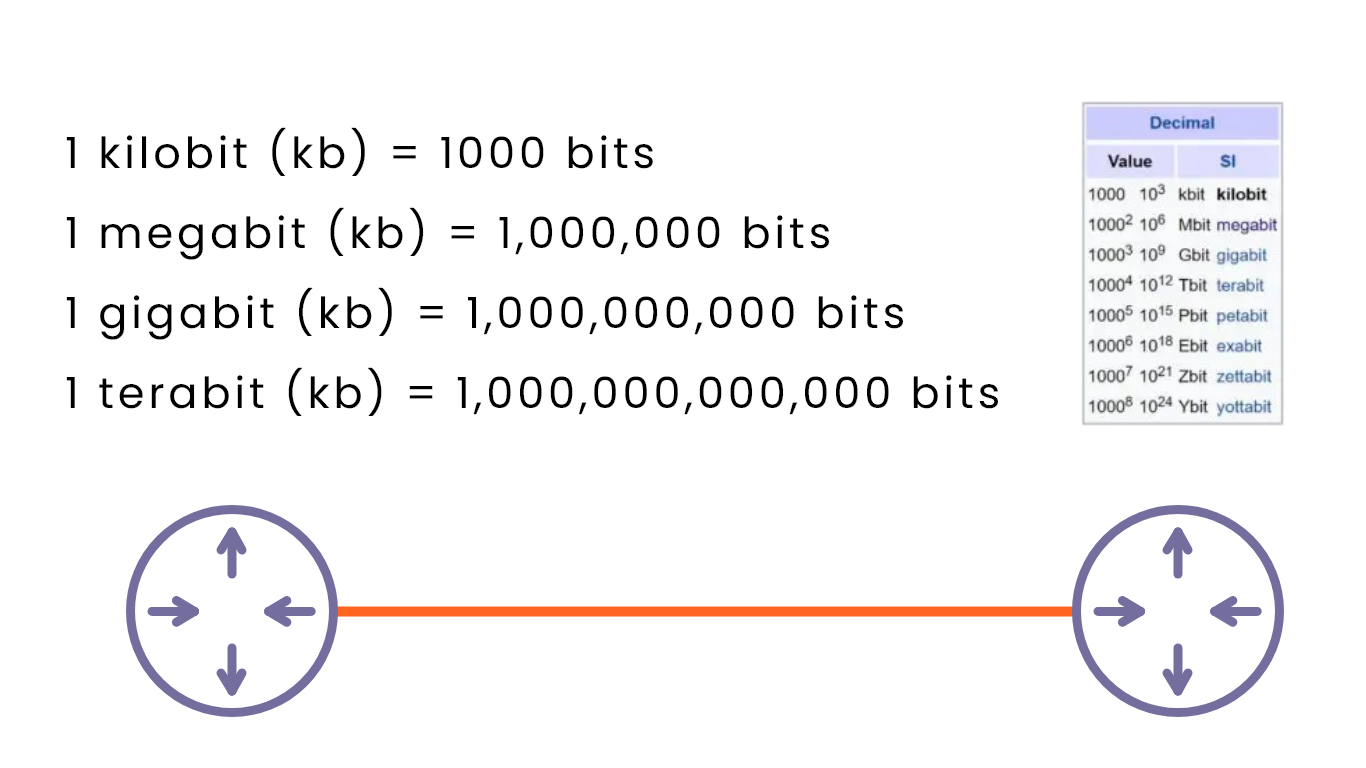
Here's a summary of common units of measurement for network speed:
- One kilobit is one thousand bits
- One megabit is one million bits (= 1000 Kb)
- One gigabit is one billion bits (= 1000 Mb)
- One terabit is one trillion bits (= 1000 Gb)
On the right side you can see some units beyond terabit, but you probably won't see speeds like them any time soon!
Note: There is a common misconception that 1 kilobit = 1024 bits, 1 megabit = 1024 kilobits, 1 gigabit = 1024 megabits, etc. This is not correct.
- The correct term for 1024 bits is 1 kibibit
- 1024 kibibits is 1 mebibit
- 1024 mebibits is 1 gibibit
- 1024 gibibit is 1 tebibit
Why 1024 instead of 1000?
It's because computers think in banry (base 2): 1024 = 210
As opposed to decimal (base 10): 1000 = 103
You can read more about binary, decimal, and hexadecimal in this article
However, network speeds are actually measured using the decimal units of 1000.
Different types Ethernet Standard (copper)
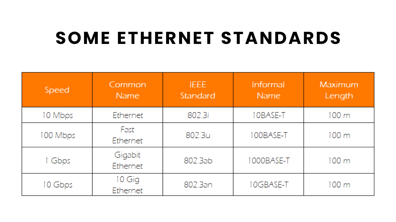
This chart shows some of the IEEE Ethernet copper cable standards. There are separate standards for fiber-optic cables, which we will address later.
For the test, it's probably no necessary to memorize the IEEE Standard names. Be familiar with the informal name (10BASE-T, etc) and also know that the maximum length for these cable standards is 100 meters (signal attenuation can occur with cable lengths greater than 100 meters).
UTP Cables
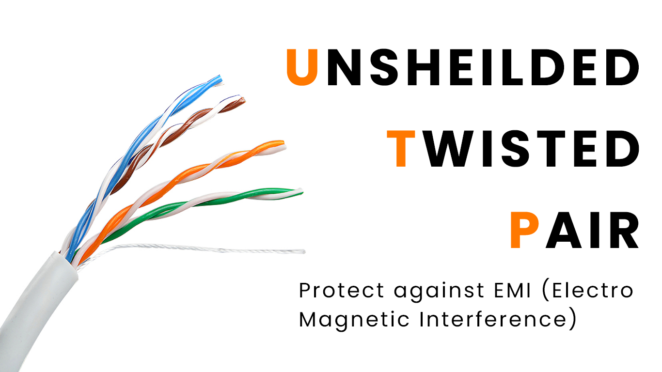
All of the copper Ethernet cable standards listed above are UTP (Unshielded Twisted Pair) cables. Unshielded means that the wires have no metallic shield, which can make them vulnerable to electrical interference. The next part of the name, Twisted Pair, however, helps with this. As you can see in the photo, inside of a single UTP cable there are four pairs of wires, and each pair is twisted together. This twist in the cables helps protect against electromagnetic interference (EMI).
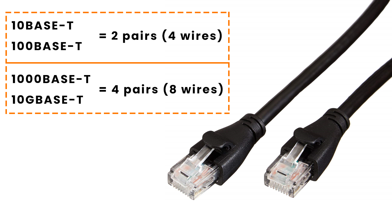
In this image you can once again see the RJ-45 connector used for an Ethernet UTP cable, with 8 pins for the 8 wires inside.
The 10BASE-T and 100BASE-T Ethernet standards only use 2 pairs of wires to transmit data, however the faster 1000BASE-T and 10GBASE-T standards use 4 pairs, all 8 wires, to transmit data.
UTP Cables (10BASE-T, 100BASE-T)
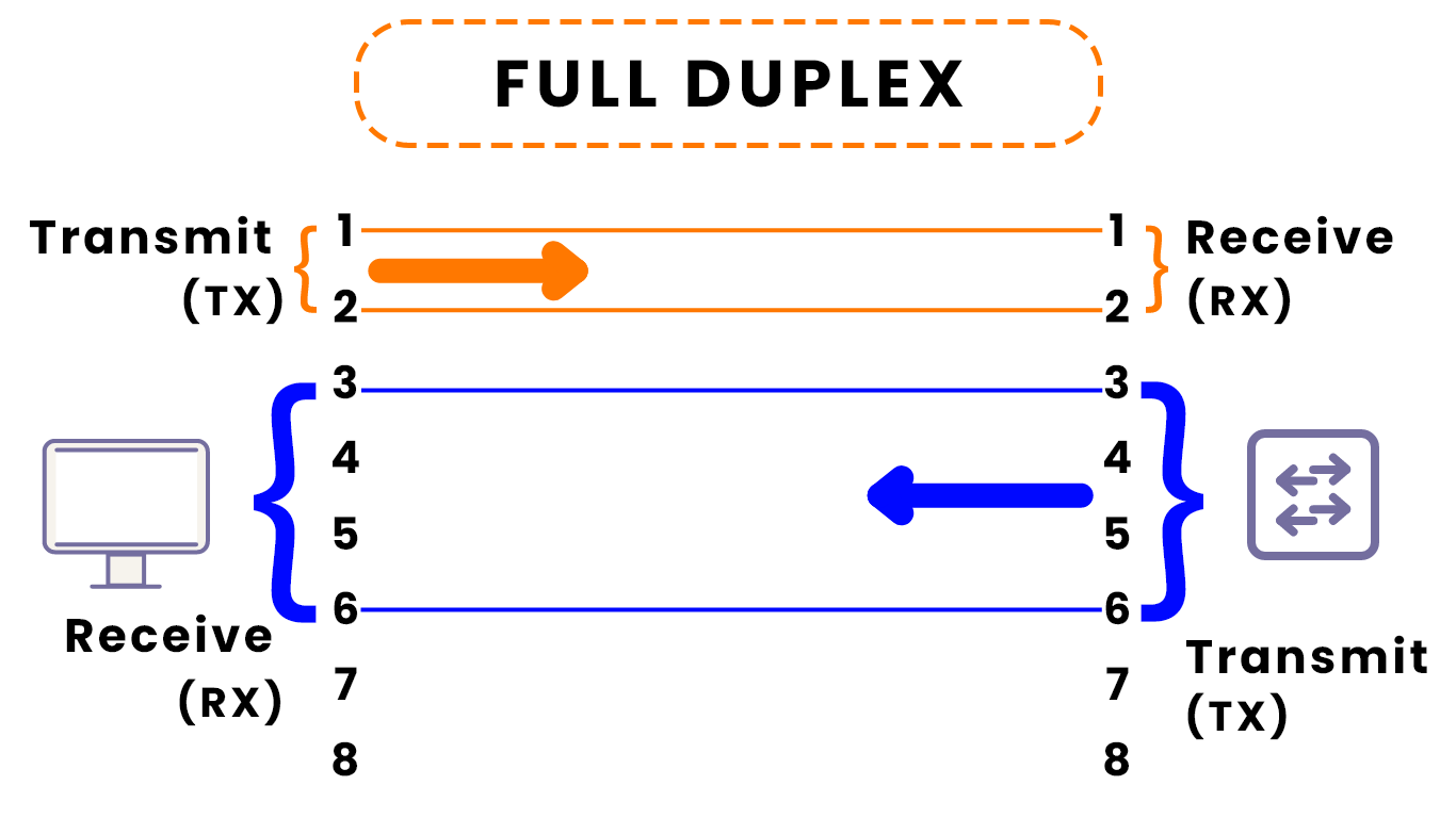
As mentioned above, the 10BASE-T and 100BASE-T standards use two pairs of wires, those pairs are 1-2 and 3-6 of the 8 wires in the UTP cable. This allows for full-duplex transmission of data. Let me defines terms below:
- Simplex: network traffic be transmitted in a single direction
- Half Duplex: network traffic can be transmitted in both directions, but not at the same time.
- Full Duplex: network traffic be transmitted in both directions at the same time.
As you can see in the image, the PC uses wires 1-2 to transmit (Tx) data, and switch uses wires 1-2 to receive (Rx) data. On the other hand, the switch uses wires 3-6 to transmit (Tx) data, and the PC uses wires 3-6 to receive data. Remember that!
- PC Wires:
1-2 = Tx,3-6 = Rx - Switch Wires:
1-2 = Rx,3-6 = Tx
Straight Through Cable
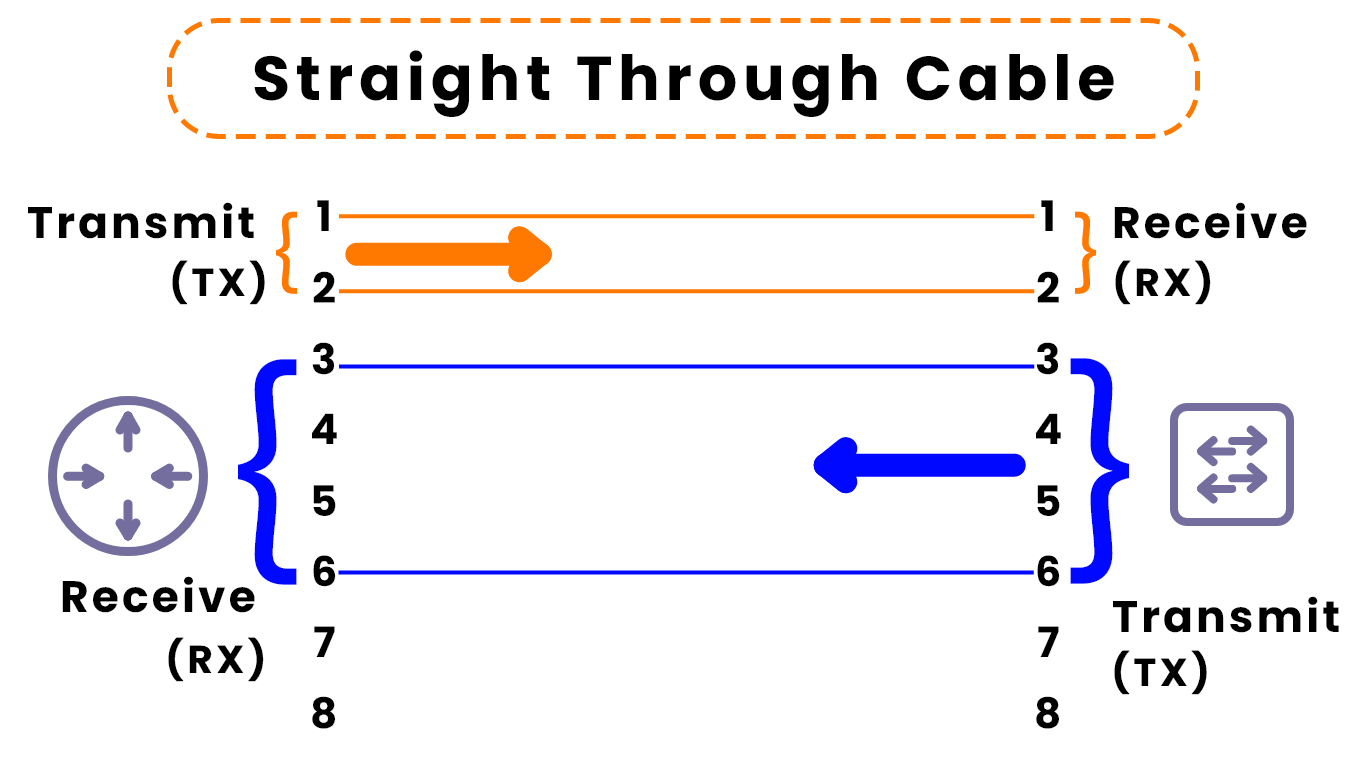
The kind of cable shown in these diagrams in called a straight-through-cable. Pin 1 on one end of the cable connects to Pin 1 on the other end. Pin 2 connects to Pin 2. Pin 3 connects to Pin 3, etc. These cables work when connecting devices that transmit/receive data on opposite pin pairs (PC-switch as shown in the previous example, or router-switch in this example).
Data transmitted on pins 1-2 of the router are received by pins 1-2 on the switch's end. Data transmitted on pins 3-6 of the switch are received by pins 3-6 on the router's end.
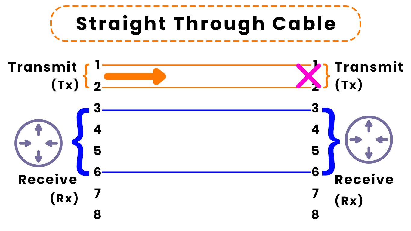
However, if we connect two devices that use the same pin pairs to transmit/receive data (for example: router-router, router-PC, PC-PC, switch-switch), we will encounter a problem. The data transmitted from one device will arrive on the Tx pins of the other device, not the RX pins. This will not allow data to be successfully transmitted and received.
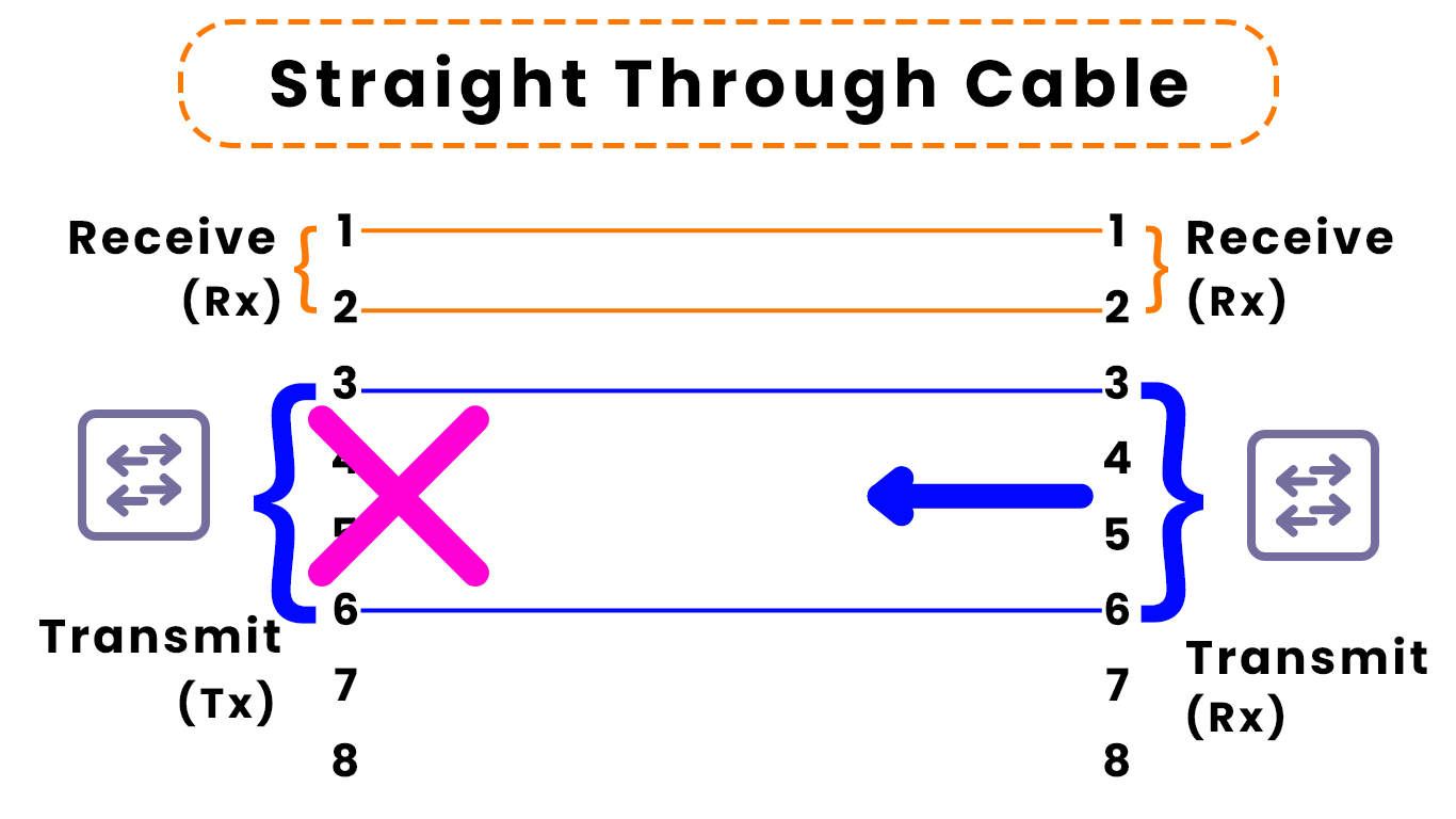
This image shows the same situation with two switches rather two routers. Data transmitted by the switch on the left arrives on the Tx pins of the switch on the right, which are not prepared to receive network traffic.
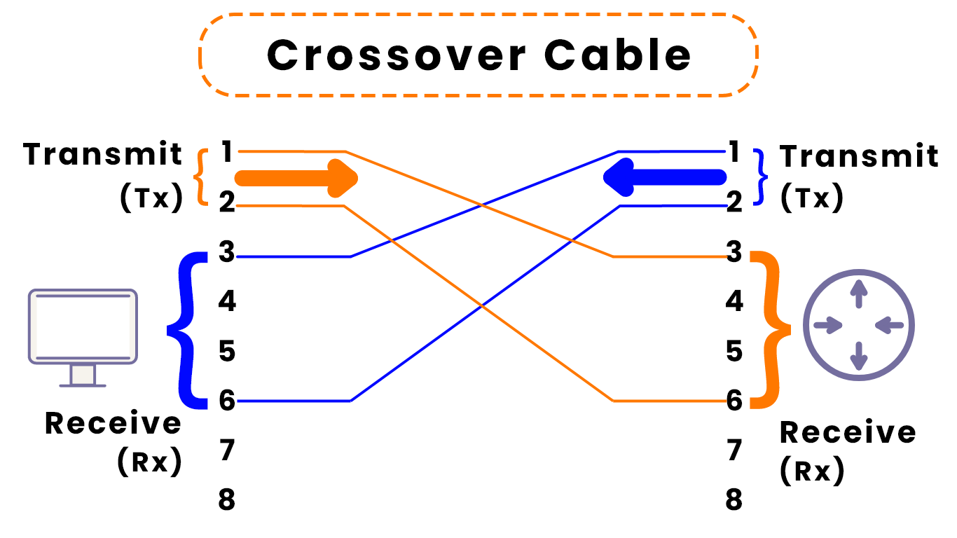
Crossover Cable
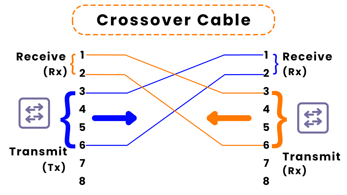
To directly connect two devices which use transmit/receive on the same pin pairs, we must use a different kind of cable called a Crossover Cable. In a crossover cable, each pin pair on one end connects to the opposite pair on the other end. Pin 1 connects to Pin 3. Pin 2 connects to Pin 6. Pin 3 connects to Pin 1. Pin 6 connects to Pin 2.
In the diagram above, the two switches can now successfully send and receive network traffic.
Here's another example. To connect a PC directly to a router, a crossover cable is needed.
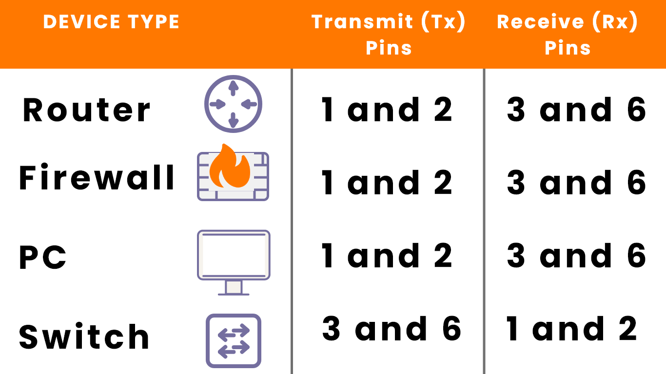
This chart outline which kind of devices transmit/receive data on which pin pairs in a UTP cable (in the 10BASE-T and 100BASE-T standards). Basically, all devices except switches use pair 1-2 to transmit and pair 3-6 to receive.
UTP Cables (10BASE-T, 100BASE-T) with Auto MDI-X
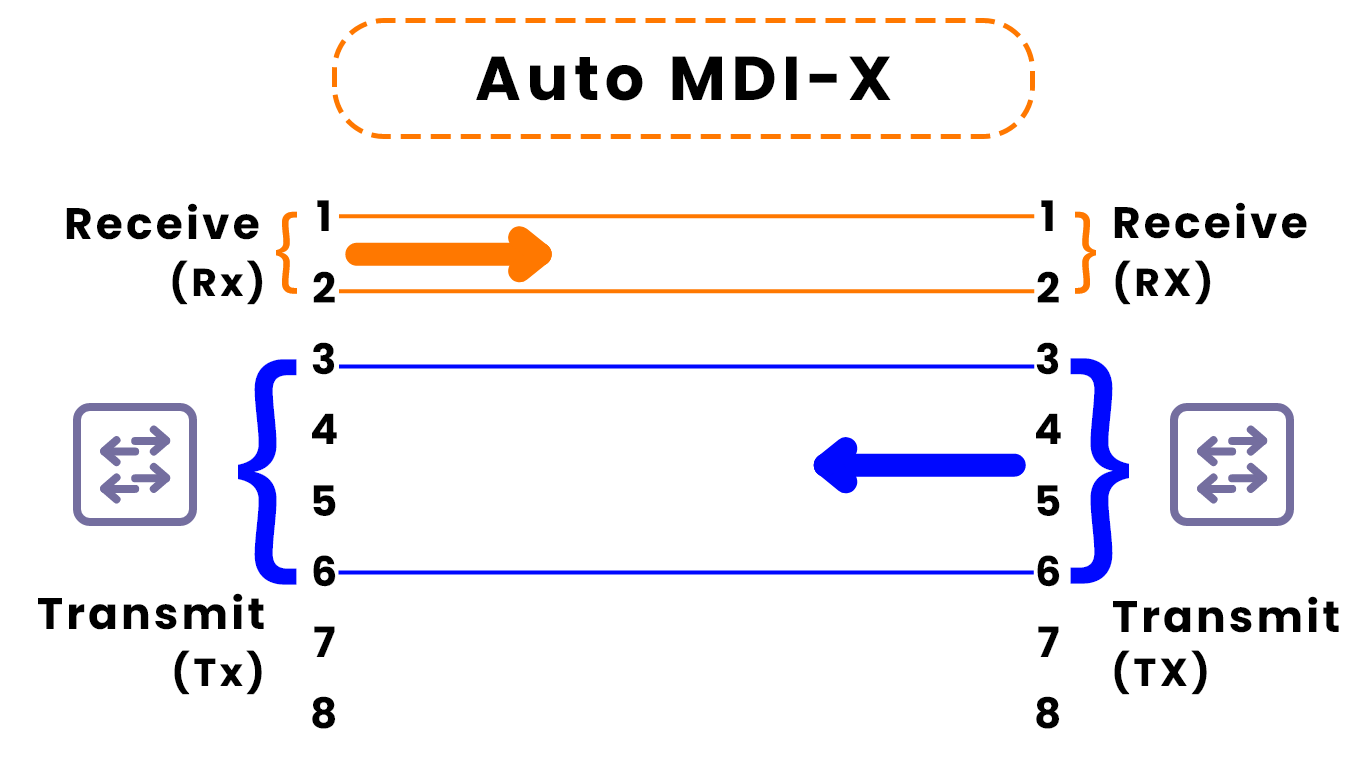
Having said all of that, there is a feature in modern network devices (actually it's been around for quite a while) that allows them to detect which pin pairs their neighbor device is using transmit/receive data, and automatically adjust which pin pairs they use. It's called Auto MDI-X.
In this image, notice that the left switch is behaving like typical switch using pin pair 3-6 to transmit data in pair 1-2 to receive data. It's connected to the right switch using a straight-through cable, which I just taught you would result in the switches being unable to communicate with each other.
However, because of Auto MDI-X, the right switch automatically adjusted its operation to transmit data on pin pair 1-2 and receive data on pin pair 3-6. So, the switches are able to communicate with no problems.
Therefore, in modern networking, it's usually not necessary to worry about straight-through or crossover cables, but you should still be aware of what I've told you in this article.
UTP Cables (1000BASE-T, 10GBASE-T)

All of the above information is about 10BASE-T and 100BASE-T connections. The faster 1000BASE-T and 10GBASE-T connections use all eight wires inside of a UTP cable.
The pairs used in addition to 1-2 and 3-6 are 4-5 and 7-8. In addition to using four pairs of wires, all eight wires in the cable, each pair is bidirectional. Any pair can be used both to send and receive data.
Fiber-Optic Connections
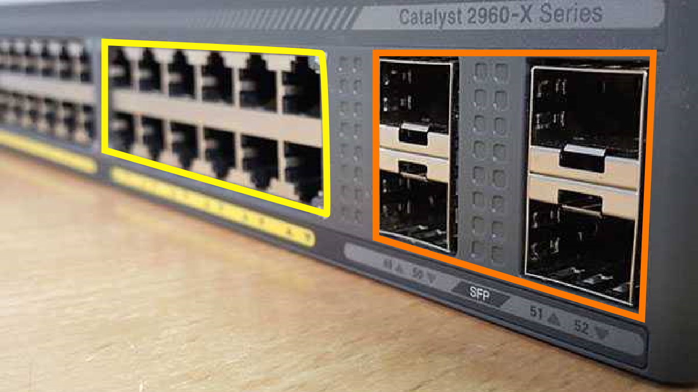
So far we've looked at copper UTP cables, which use RJ-45 connectors to connect to the ports in the yellow boxes in this image. The ports in the orange boxes use a newer, totally different kind of cable, which I will introduce now.

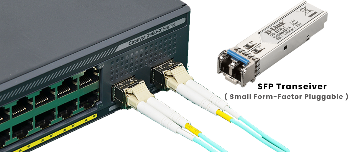
Into those slots you insert an SFP (Small Form-Factor Pluggable) transceiver. These are used to connect network devices using this new kind of cable.
This new kind of cable I'm referring to is: fiber-optic. Fiber-optic cables contain a very fine glass fiber which is used to transmit light, rather than transmitting electricity along a copper cable.
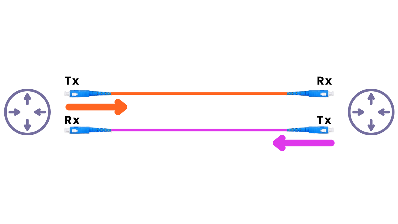
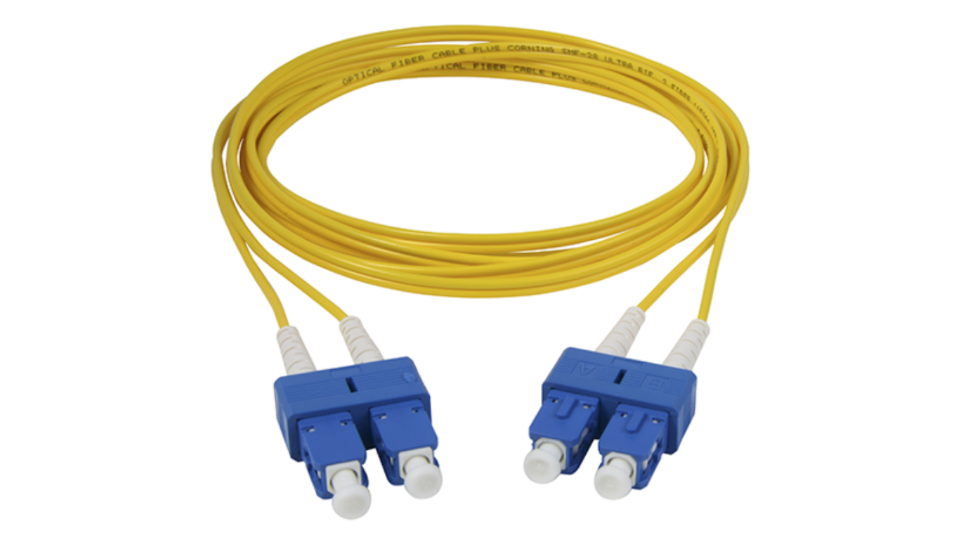
Unlike UTP cables, which contain multiple wires within each cable, each fiber-optic cable contains a single glass core. So, each cable is unidirectional. Therefore, for each connection you need two cables, as shown in the diagram above.
The router on the left uses the red cable to transmit data and the blue cable to receive data. The router on the right does the opposite.
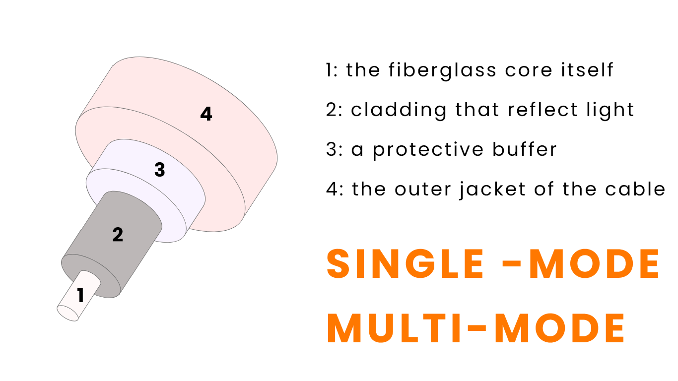
This diagram shows the structure of a fiber-optic cable.
- In the very middle is the fiber of glass itself, used to transmit the light signals.
- Next is cladding which reflects light.
- Then there is a protective buffer, to prevent the glass core from breaking.
- Finally, the outer jacket of the cable.
There are two main types of fiber-optic cables: single-mode and multimode. I'll explain both types.
Multimode fiber-optic cable
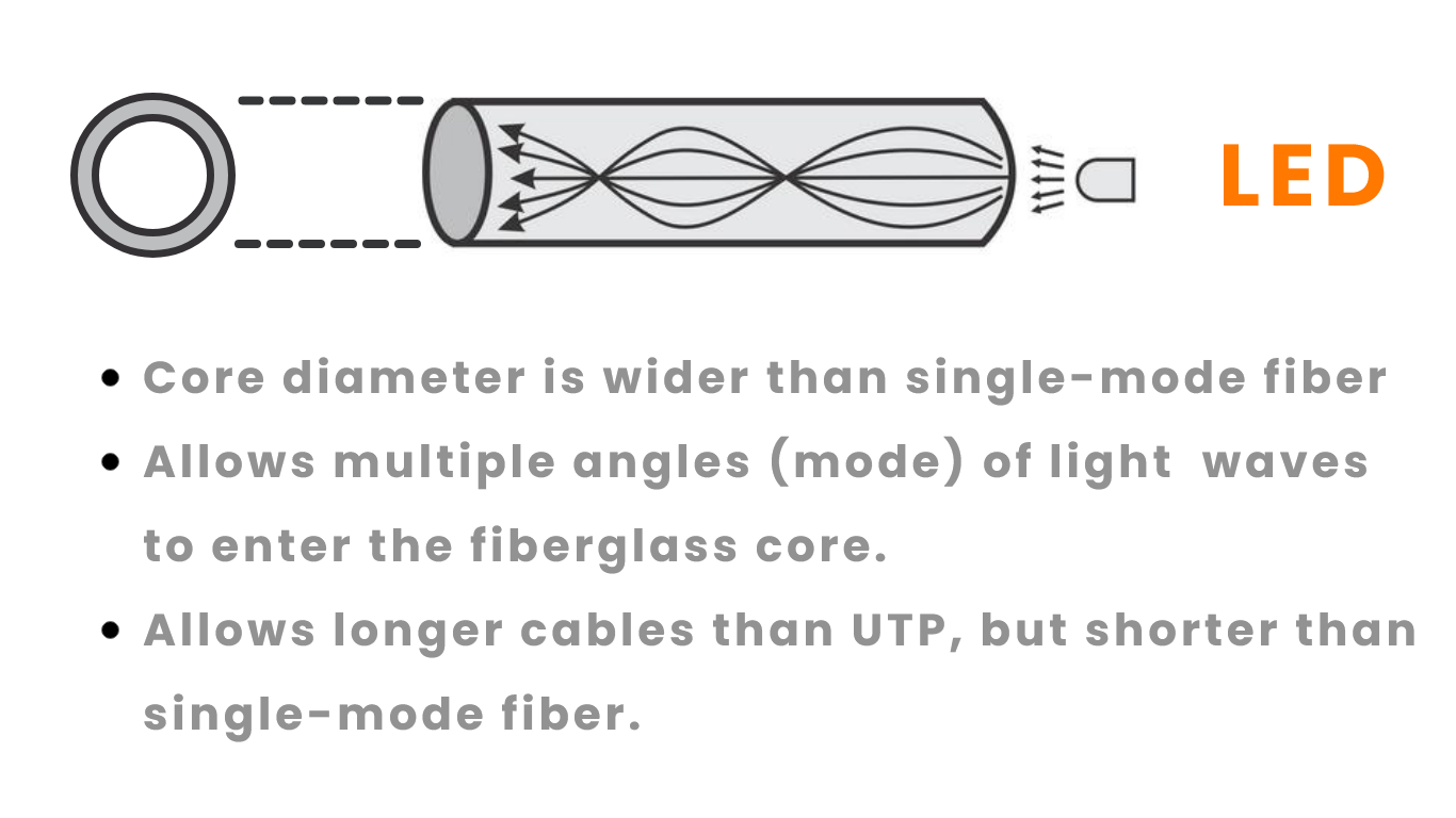
Multimode fiber-optic cables use a glass core with a wider diameter than single-mode fiber cables. This wider core allows multiple angles (called modes) of light waves to enter (thus the name, multimode)
Multimode fiber cables allow longer cable length than UTP(100 meters), but shorter than single-mode fiber cables. Below I will show a chart of some different standards for fiber-optic cables so you can compare the maximum lengths. Multimode fiber cables are also cheaper than single-mode.
Single-mode fiber-optic cable
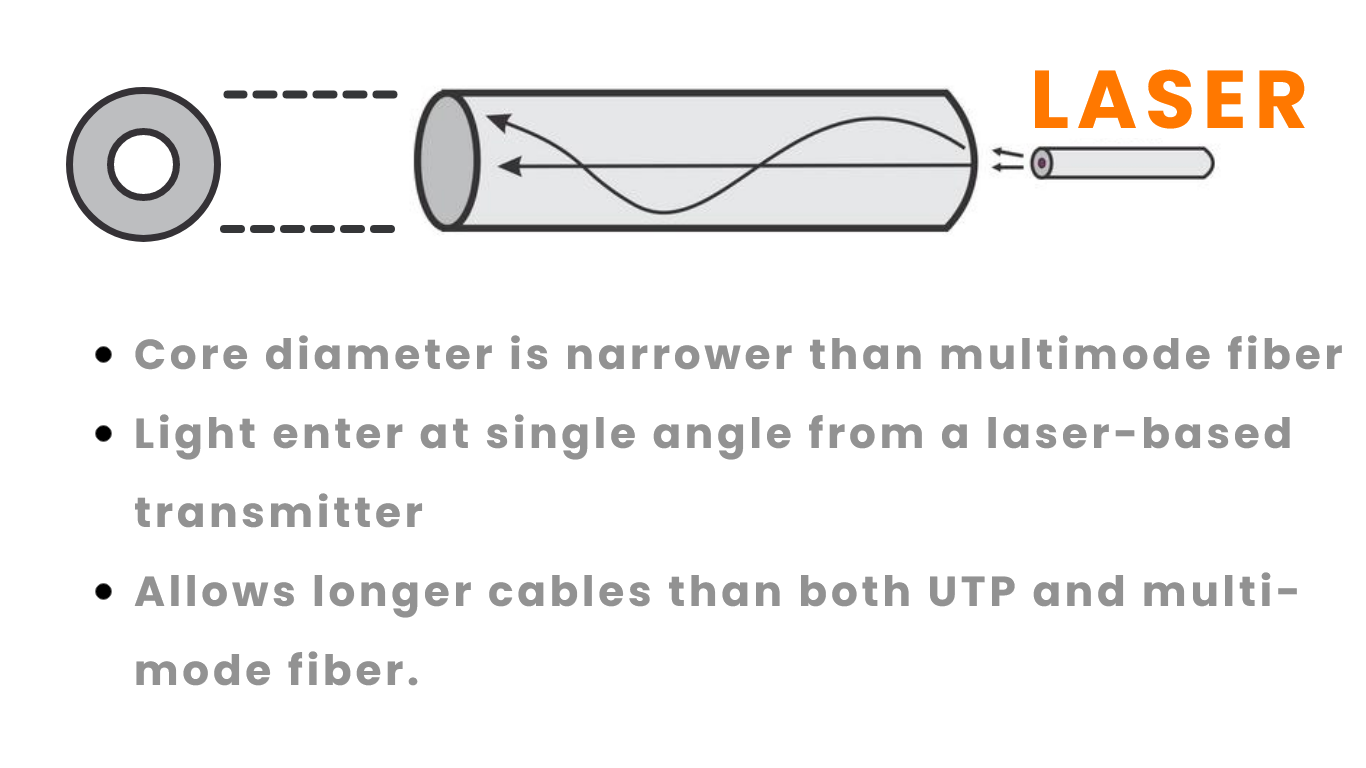
Single-mode fiber cables use a narrower core, and light enters a single angle(mode). In this image, the top diagram shows single-mode fiber cable.
Single-mode fiber cables allow for longer cable length than multimode but are more expensive.
Fiber-Optic cable Standard
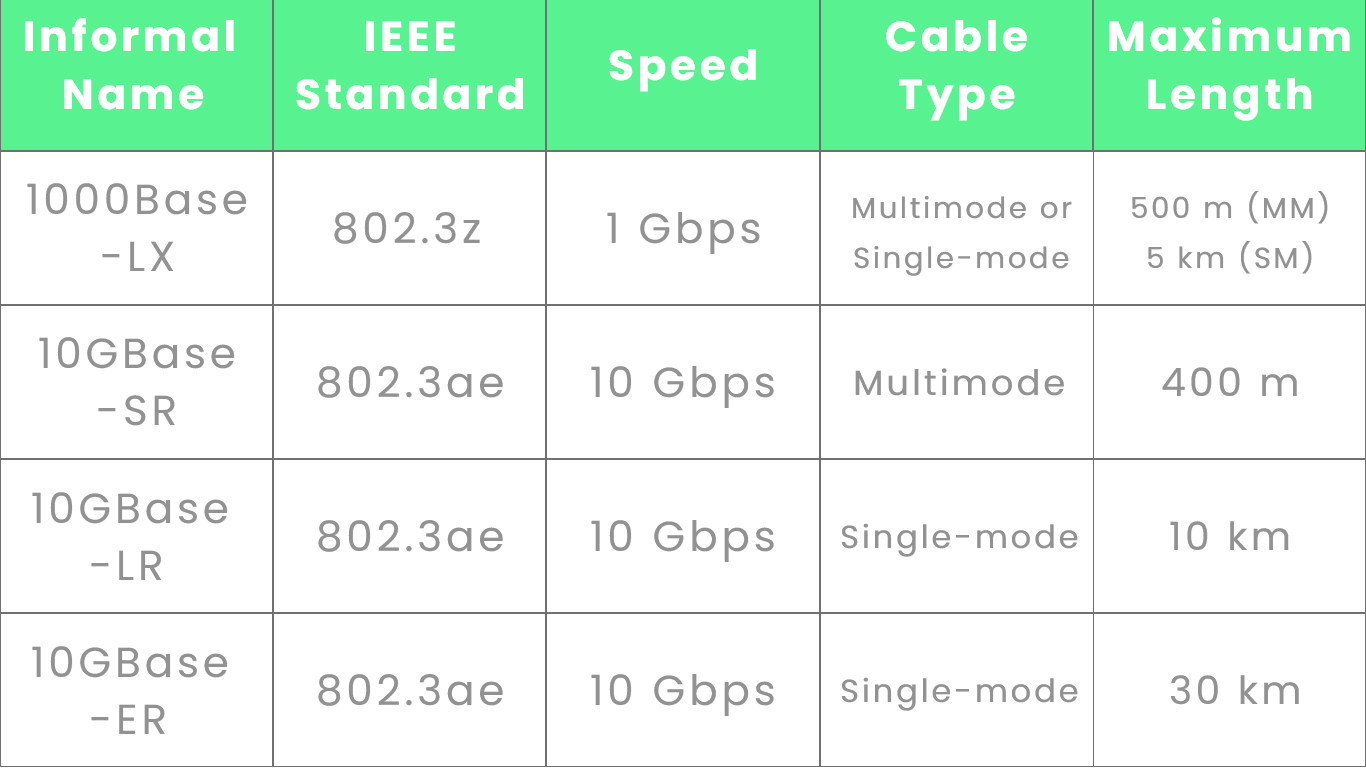
This chart displays just a few of the Ethernet standards for fiber-optic cables. It's most likely not necessary to commit all of these to memory for the exam. Just remember that multimode fiber allows for cable lengths up to hundreds of meters, while single-mode fiber can support lengths up to tens of kilometers.